For dynamic field balancing, it is crucial to determine the actual effective point of unbalance in first round so that trial weight can be removed from this point of unbalance or added 180 degrees opposite to that point. Actual point of unbalance is the net effect of uneven mass distribution on the rotating body. Removing weight from this point will reduce the net unbalance of the rotating body. This is also equivalent to adding weight 180 degrees opposite to the actual point of unbalance. This has two advantages:
- Removal of trial weight will NOT increase vibrations due to unbalance. This is very useful in case of high speed machines and where field balancing needs to be performed in minimum number of trial rounds. If vibrations increase, then other causes of vibrations needs to be analyzed.
- Problems due to tachometer like dependency on light conditions, mounting requirements, safety of tachometer and setup time are eliminated since automatic balancing uses external stroboscope.
Automatic field balancing combines the real time processing capabilities of digital world with the ease of use of visually locating point of unbalance of classical world.
Field balancing using tachometer
This article discusses and compares single plane balancing techniques. Various techniques have been experimented to reduce the number of trials required before determining the actual point of unbalance. One of the techniques uses a laser guided optical sensor (also called as tachometer) for speed detection, synchronization and marking a reference point (also called as zero point) on the rotating body. Single plane balancing using this technique has 3 steps:
- Initial round wherein initial amplitude and phase of vibration unbalance are measured
- Trial round wherein a known trial weight is added at an arbitrary location and the corresponding change in amplitude and phase of unbalance is recorded.
- Final round wherein correction weight and its location is calculated.
Drawbacks of field balancing using tachometer
This being one of the most widely implemented technique but with some shortcomings:
- Adding trial weight may cause vibrations to amplify in certain situations. This might increase the overall vibrations above tolerance and increase risk of damage in high speed machines, e.g. de-canters, spindles, etc.
- Trial weight needs to be removed to add correction weight.
- Setup time for tachometer is high. Reflectivity and light conditions create problems for synchronization signal, for example : in case of cooling towers. Also, loose mounting causes additional problems.
Field balancing using stroboscope
An traditional field balancing technique which uses stroboscope for locating the point of unbalance determines the absolute point of unbalance in first round. Simple? Then why isn't it widely used these days? Because it was tiresome and required manually tuning stroboscope for speed synchronization and then manually locating maximum amplitude point for field balancing. Also older discrete analog technology had limitation with filter selection and FFT processing. The bright side being convenience : it is easy to visually locate point of unbalance than to measure in degrees since locating exact angle position on an installed rotor is tedious, for example, locating 42 degrees on a rotor without any measuring instrument is tedious.
Concept and advantages of automatic field balancing
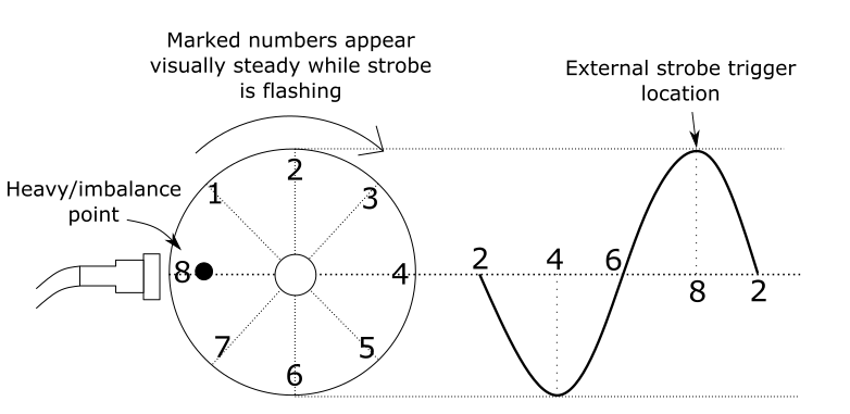
Automatic field balancing combines the best of both world. The concept is simple : "Unbalance occurs at machine speed only and for dynamic field balancing it should be the major cause of vibrations". Figure 1 below shows the setup required for Automatic single plane field balancing. Accelerometer mounting position should be horizontal. Graphical markings are done at equidistant angle on the rotating object. The numbers will not be visible when the object is in rotation.

Using advanced digital techniques and our proprietary algorithm, automatic balancing analyses and extracts machine speed from vibration unbalance signal. Reference point or the zero point is always vibration accelerometer which is used for synchronization. The point of maximum vibration amplitude is the location of effective point of unbalance as seen below. External stroboscope is triggered whenever the point of unbalance is at the zero point of accelerometer location. Figure 2 below shows the concept of locating the point of unbalance using Automatic single plane field balancing with respect to the accelerometer when the external stroboscope is flashing. Read more about using stroboscope for field balancing under different circumstances on our blog Industrial blower impeller field balancing using stroboscope
Portable balancing machine
Below is an overview of procedure for single plane field balancing. Refer product user manual for detailed instructions. metro B6012 vibration analyzer and balancer implements proprietary automatic 2-round single plane field balancing and FFT vibration analysis. It comes with accelerometer, it's connecting cable, mounting magnet, stroboscope, it's connecting cable and power cord, battery and charger.
Single plane field balancing procedure
-
Setup for field balancing
- Mount the accelerometer as per requirement on a stationary housing closest to the rotating machine under maintenance. It may be a bearing housing or motor housing. Connect it to metro B6012.
- Connect stroboscope with metro B6012 using connecting cable. Connect stroboscope to external AC power supply using power cord and power it ON. Press the EXT trigger button on stroboscope to use it with metro B6012.
- Mark equidistant numbers/alphabets (as shown above) on the rotating shaft to locate the point of unbalance by stroboscope.
-
First run
- Power ON metro B6012.
- Select Balancing sub-menu in main menu by pressing OK key. Select Automatic balancing sub-menu in Balancing menu using OK key. It is the start of first field balancing round.
- Select preferred unit for field balancing.
- Select convenient method of locating the point of unbalance: add or remove location for trial weight. Press OK key.
- metro B6012 will determine and display stable speed and amplitude from vibration unbalance signal automatically using above mentioned proprietary technology. Point of unbalance is indicated by stroboscope. Press OK key to acknowledge these values.
- Add/remove trial weight at the point of unbalance indicated by stroboscope. Enter this value in the instrument and press OK key. This will start second round.
-
Second run
- metro B6012 will again calculate and display stable speed and amplitude from vibration unbalance signal automatically. Point of unbalance will be indicated using stroboscope. In addition, it will calculate and display the final weight required to be added/removed at the current point of unbalance for complete the field balancing process.
- Add/remove the final weight in addition to the trial weight at the indicated point of unbalance. Press OK key to acknowledge these values and save field balancing data.
-
Vibration analysis after field balancing
- Vibrations due to unbalance of the rotating machine should be reduced within tolerance levels with this field balancing process.
- If you further need to reduce remaining vibrations due to unbalance, repeat the field balancing process.
Watch the automatic 2-round dynamic field balancing demonstration video above to see how it works and how to visually locate point of unbalance. metro B6012 is the easiest to use vibration analyzer and balancer suitable for periodic condition monitoring and field balancing of rotors, blowers, impellers, cooling towers, industrial fans, HVAC systems, motors, pumps, grinders, crushers, mixers, spindles and similar rotating machine structures.